Total Solar Irradiance Record
The total solar irradiance (TSI) climate data record began with spacecraft measurements over 33 years ago. While each instrument contributing to the record demonstrates the sensitivity to detect small changes in the Sun’s radiant energy and most can even track internal on-orbit degradation, the offsets between these instruments on an absolute scale generally exceed the stated instrument uncertainties.
As a first step to address these offsets, optical power comparisons of the ground-based Witness unit of the Total Irradiance Monitor (TIM) currently flying on the SOlar Radiation and Climate Experiment (SORCE) were compared against a NIST optical power standard at NIST/Gaithersburg in 2006. A follow-on step was to address the comparisons in irradiance, rather than optical power, mode. The NASA Glory mission funded the creation of the TSI Radiometer Facility (TRF), designed and completed at LASP in 2008, making it the only calibration facility in the world able to characterize TSI instruments at the desired accuracy (0.01% absolute accuracy) and power levels under flight-like vacuum conditions.
TSI Radiometer Facility (TRF)
Instruments characterized at LASP’s TRF include the Glory Total Irradiance Monitor (TIM), the PREcision Monitoring Sensor (PREMOS) instrument from the Physikalisch-Meteorologisches Observatorium (PMOD) institute in Davos, Switzerland, a ground-based PMO-6 instrument similar to that flying on the Solar and Heliophysics Observatory (SOHO), an Active Cavity Radiometer Irradiance Monitor (ACRIM) instrument, and the Total Solar Irradiance Sensor (TSIS) TIM instrument.
As an end result, the TRF:
1. Improves the calibration accuracy of future TSI instruments,
2. Establishes a new ground-based radiometric irradiance reference standard, and
3. Provides a means of comparing existing ground-based TSI instruments against this standard under flight-like operating conditions.
Results
Experiments performed at the TRF have confirmed that erroneous increases in TSI signal occur from uncorrected diffracted and scattered light.
All TSI instruments except the TIM put their primary precision aperture close to the radiometer cavity, which results in an overfilling of the view-limiting aperture allowing additional light into the instrument and an erroneous increase in measured signal due to uncorrected scatter and diffraction of light from the front and interior sections of the instrument. The required correction has reached 0.51% in some cases.
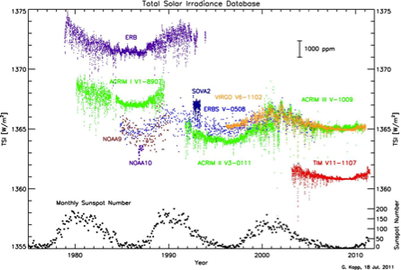
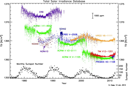
In the left plot, none of the instruments measuring total solar irradiance (TSI) have been validated end-to-end for irradiance to the desired accuracies. In the right plot, TRF corrections have been applied to ACRIM and PREMOS data to account for diffracted and scattered light. (Plot last updated March 2012).
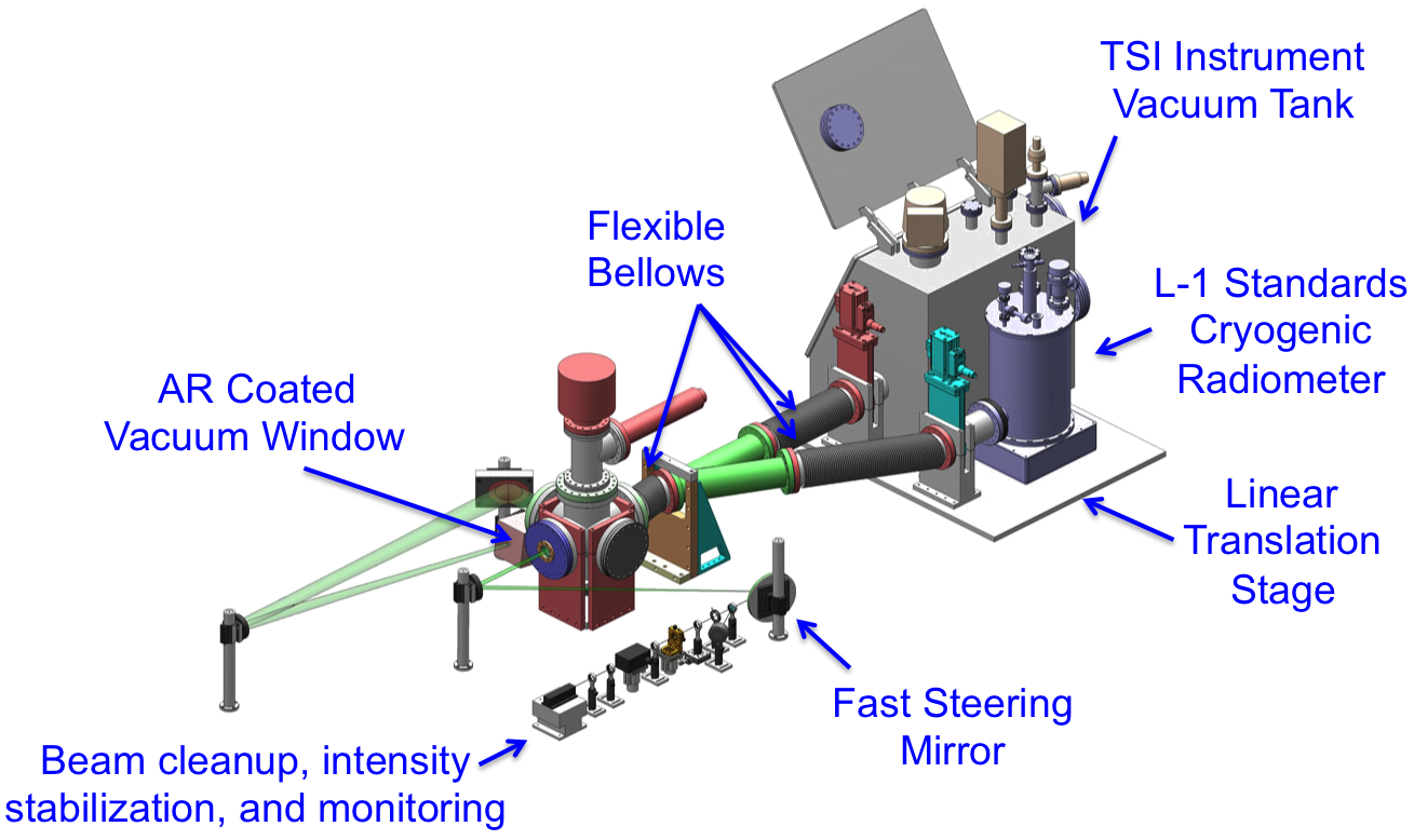
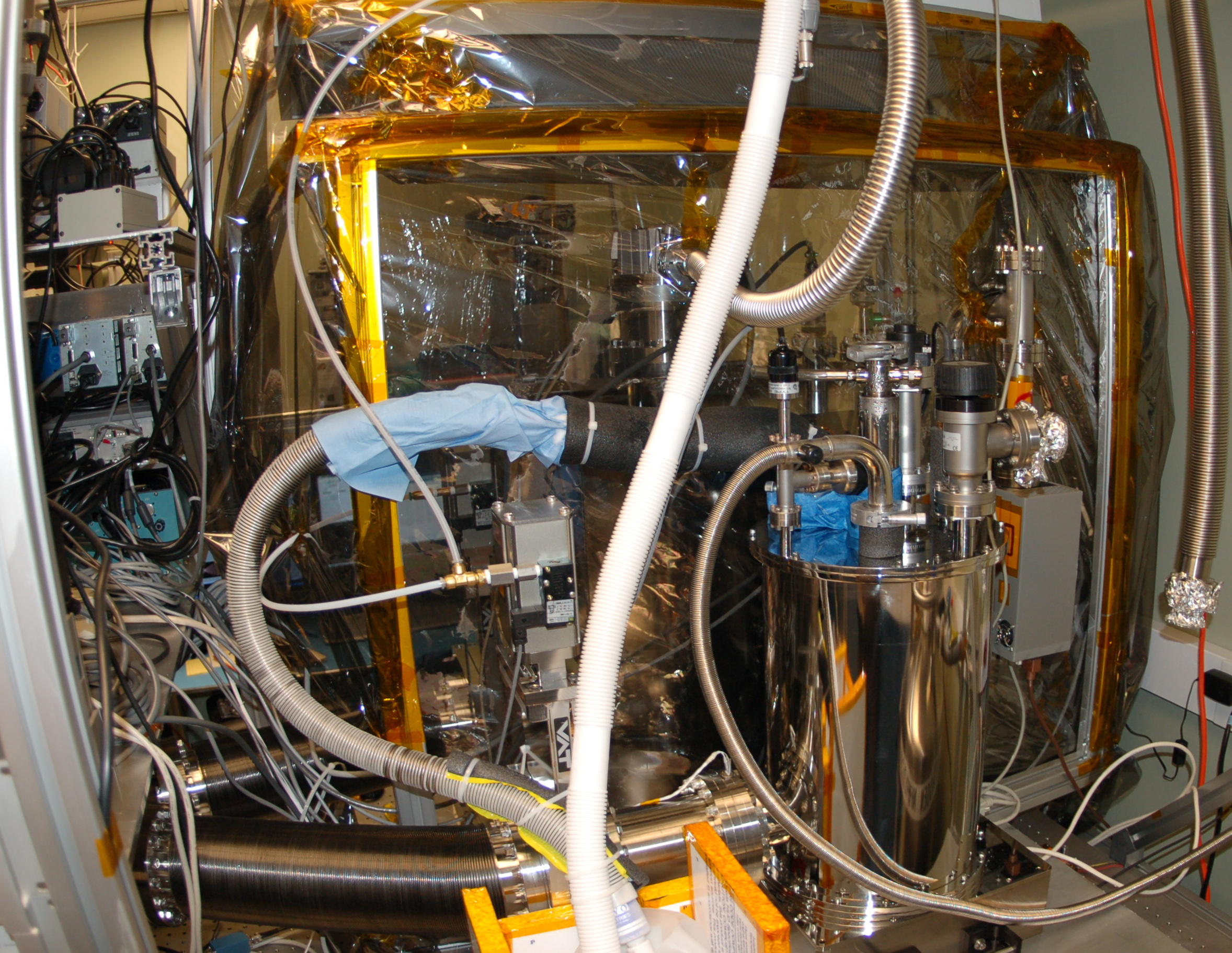
Design
The TRF is designed to perform irradiance comparisons of TSI instruments to a reference cryogenic radiometer. It has:
- a custom-built solar-power level cryogenic radiometer as an absolute reference,
- an instrument tank designed to accommodate TIM and other TSI instruments to perform all tests in vacuum, simulating flight conditions,
- a common vacuum system and beam path that reduces optical differences in comparisons and,
- a uniform aperture illumination at solar power levels generated using beam scanning technique.
The design allows either the precision aperture of the cryogenic radiometer or a TSI instrument to be placed at the same spatial location in the stationary beam.
A uniform beam is generated by scanning a smaller beam in a spiral pattern using a fast steering mirror. The instrument response time exceeds the scan period.