
EPS
Electrical Power System
 The SNOE Electrical Power System (EPS) is a direct energy transfer system that generates energy, stores energy for use during orbit eclipse, and controls the distribution of energy to the required S/C and payload systems. Design goals for the EPS include generation and distribution of reliable 28V (plus or minus 4V) power to the S/C and payload with a greater than 20% end of life (EOL) margin. Much of the SNOE power system design is modeled after the Solar Mesosphere Explorer (SME) spacecraft EPS.
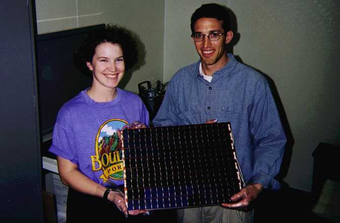
Power is generated by body mounted panels of solar arrays. There are twelve rectangular panels, each containing 2 array circuits (strings) for total of 24 strings. The strings consist of seventy-four 2.3 cm x 4.1 cm silicon photovoltaic cells. Diode isolation of the individual array circuits from the bus is used to prevent a failure in an array string from causing a failure of the entire power generation system. Assuming one-year degradation of 10% and 30 degree solar beta angle, the solar arrays will generate greater than 42 watts orbit average power at EOL.
The solar cells were purchased from Heliokinetics of Palm Springs, CA. The 10 Ohm-cm, 8 mil. thick cells are AR coated and delivered with pre-installed cover glass and interconnection butterfly fittings. Criteria and procedures for selection of the individual flight solar cells include testing for cell open circuit voltage and short circuit current. Assembly of the arrays was performed by student assemblers (trained by industry consultants) at LASP under the supervision of LASP QA personnel.
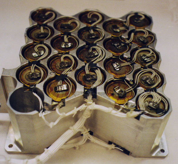
Energy required for peak loads and during the eclipse portion of the orbit is stored in two 22-cell 4-Amp-hour Nickel Cadmium (NiCd) battery packs. The batteries use Sanyo D cells, tested, integrated and qualified by a flight proven Ball Aerospace process. With exception of telemetry transmission, the S/C and payload have static power usage profiles. There are no diurnal or seasonal experiment scenarios. The transmitter draws 28W during transmission, which occurs twice per day for less than 20 minutes per pass. Total orbit average power required is 35 watts. This power usage produces a battery depth of discharge (DOD) of less than 10%. Typical life for a NiCd battery operated at <20% DOD is >20,000 charge/discharge cycles (>3 years).
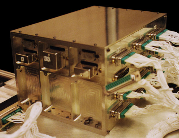
A shunt regulator is used to prevent overcharging of the battery and the associated generation of excess heat. Shunt regulation is performed by clamping the bus voltage to a level set by predetermined voltage and temperature curves (V-T control). Bus clamping action (regulation) is implemented by a two mode shunt controller which uses a combination of conventional linear shunt regulation (fine control mode) along with solar array string circuit switching (coarse control mode). The coarse control is achieved using switched array string circuits controlled by the V-T controller in a closed loop fashion. There are three switching circuits of six strings each, with the six strings distributed one to each S/C face to prevent current fluctuation when one or more circuits are switched off. Fine control is performed by a linear regulator that shunts excess power into resistors mounted on S/C surfaces. The V-T controller uses 4 temperature voltage curves selected by uplink command. Power distribution includes two primary power busses; the essential bus and the non-essential bus. Circuits on the essential bus are the EPS itself, the command receiver/demodulator, and the S/C processor. All other loads are considered non-essential and are therefore disconnected when the bus voltage monitor detects a low voltage condition. Because EPS reliability is of primary importance to the spacecraft, the power control unit has some redundant components in critical areas.