Figures
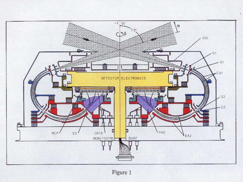
Figure 1: Ion Optics
Schematic cross section of the TIMAS ion optics. Elements include the collimator (COL), ion repeller (C1), object slit (S1), first toroidal electrostatic analyzer (EA1), image slit for EA1 (S2), first field terminator for EA2 (C2), second toroidal electrostatic analyzer (EA2), second field terminator for EA2 (S3), sector magnets (MAG), grid assembly (GRID), microchannel plate (MCP) detector, and detector electronics. The entire assembly is rotationally symmetric about the vertical center line.
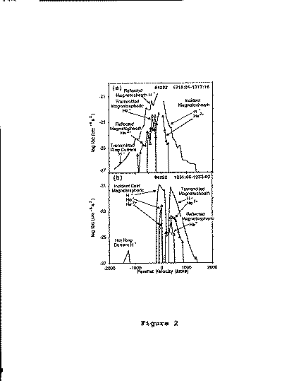
Figure 2: Ion distributions expected near the magnetopause
Parallel cuts through the H+, He2+, and He+ distributions in the accelerated flow region (a) outside, and (b) inside the magnetopause [from Fuselier et al., 1991].
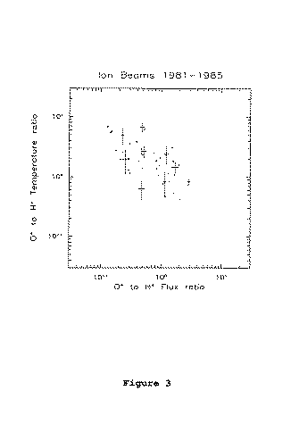
Figure 3: O+/H+ Temperature and flux ratios expected in auroral ion beams
Figure 3:Scatter plot of O+ to H+ temperature ratio versus O+ to H+ flux in auroral ion beams, demonstrating their correlation [from Collin et al., 1987].
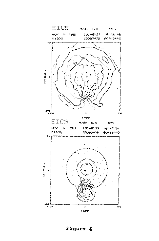
Figure 4: Velocity space density contours expected in auroral ion beams
Velocity space contours for the H+ (top) and O+ (bottom) components of an auroral ion beam. The velocity of the H+ is approximately four times higher than that of the O+ beam, consistent with acceleration through an upward parallel electric field [from Reiff et al., 1988].
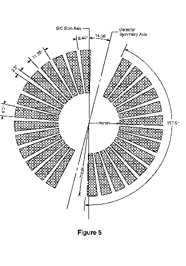
Figure 5: Geometery of the Multi Channel Plate (MCP) detector
Velocity space contours for the H+ (top) and O+ (bottom) components of an auroral ion beam. The velocity of the H+ is approximately four times higher than that of the O+ beam, consistent with acceleration through an upward parallel electric field [from Reiff et al., 1988].
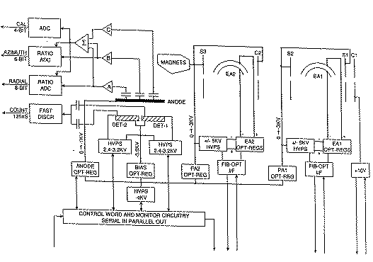
Figure 6: High voltage and detector analog diagrams
Block diagram of the high voltage system and detector analog electronics.
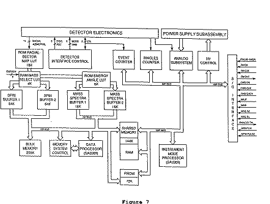
Figure 7: Instrument control and data processing diagram
Block diagram of instrument control and data processing system.
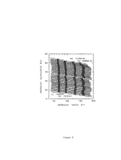
Figure 8: Mapping detetector signals to mass angle steps
Template for associating detector radial and azimuthal signal bins with mass step (actually rigidity bin; vertical bands), and field-of-view sector (horizontal bands). Shaded bands represent a subset of the ion calibration data used to infer the loci of constant rigidity (energies are internal to the instrument). While centered according to calibration, these bands have a width estimated from theory to be the full width at 50% of maximum response (about equal to 2/3 of full width at 0.1% of maximum; see text for calibration limitations).
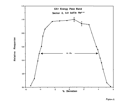
Figure 9: Energy response
Energy passband of the ESA-1 measured at the midplane of sector 3. ESA plate voltages were varied while holding the Ne2+ monoenergetic ion beam at a constant 3 keV/e normal to the entrance aperture. Characteristic counting statistical errors are shown.
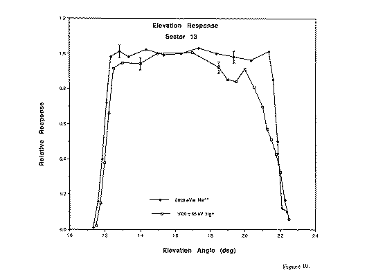
Figure 10: Elevation (alpha) angle response
Elevation angle (alpha) response measured at the midplane of sector 13. The solid dots were measured with a monoenergetic Ne^2+ ion beam at 3000 eV/e. The open square data points were measured with an H2+ beam having a broad (13%) energy spread about the nominal energy setting of 1000 eV for the ESAs.
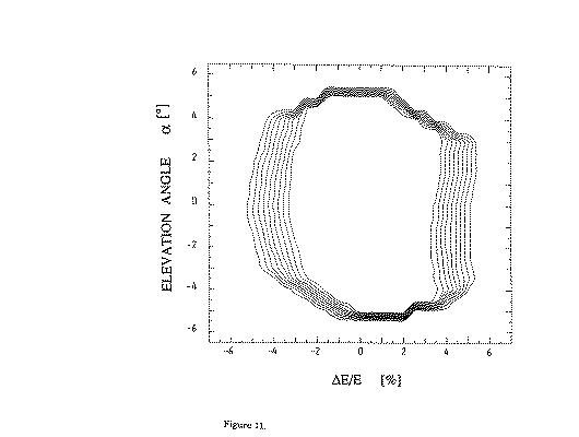
Figure 11: Energy-angle response
Contour plot of the predicted energy-angle transmission function for the TIMAS instrument. Contours are at 10% intervals from 10% to 90%. The double focusing results in nearly complete independence of energy and angle parameters
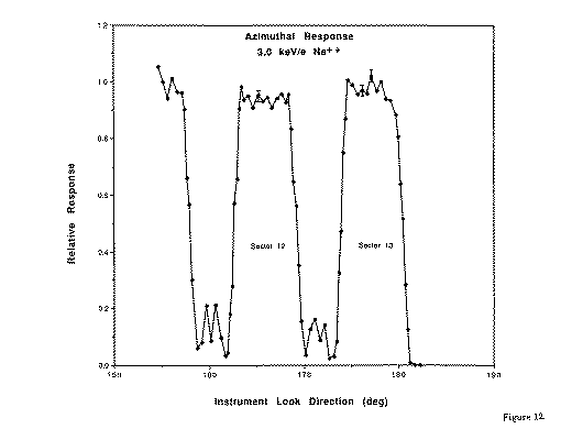
Figure 12: Azimuthal response
Characteristic azimuthal response of the TIMAS instrument to monoenergetic 3.0 keV/e Ne^2+ ions incident normal to the entrance aperture (S1), measured with no preacceleration. An angle of 180 degrees corresponds to ions coming from the spacecraft spin axis direction. Error bars indicate characteristic one sigma counting statistics.
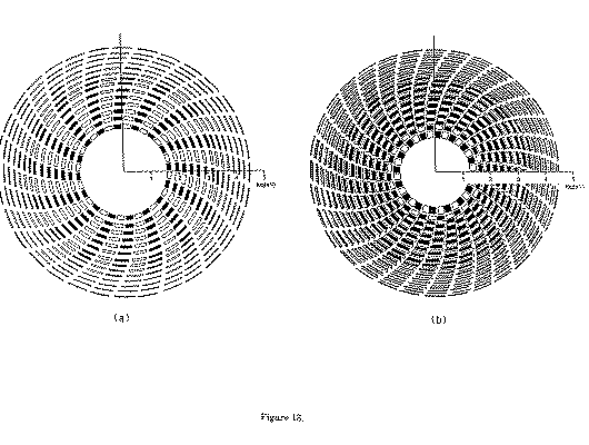
Figure 13: Energy-angle coverage in the standard science mode
Energy versus spin angle coverage near the spin plane in the standard science mode; a) during a single odd spin period and b) over two consecutive spin periods. The open arc segments are coverage by one MCP detector half and the solid segments are coverage by the other detector half. The radial distance is proportional to the log of the energy per charge (eV/e). Coverage is similar for elevation angles away from the spin plane but with some overlap.

