
1: Receiver Construction
by Lucy Todd, Summer 2016.
Soldering the PC board
On Monday the 13th, the Radio JOVE kit arrived at LASP! As quoted from their about page, the Radio JOVE project is a “hands-on, inquiry-based educational project that allows students, teachers and the general public to learn about radio astronomy by building their own radio telescope”. They provide a non-profit radio telescope kit available to purchase online, which is the kit that I will be using to construct my own telescope.
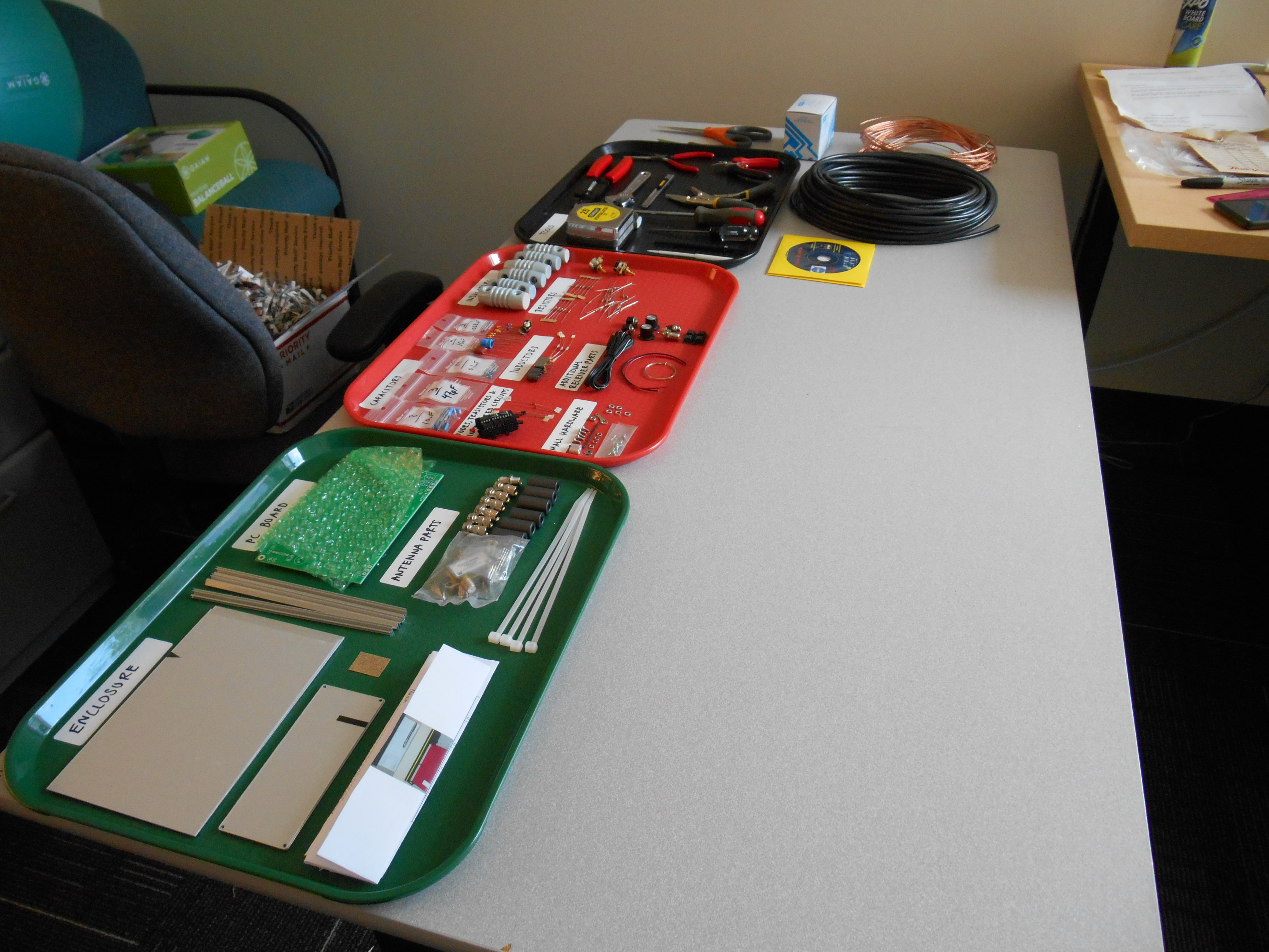
When the kit arrived, I first set about organising the many, many components and tools, and reading the two assembly manuals provided: one for antenna construction, one for receiver construction. Thankfully an extensive check list was provided.
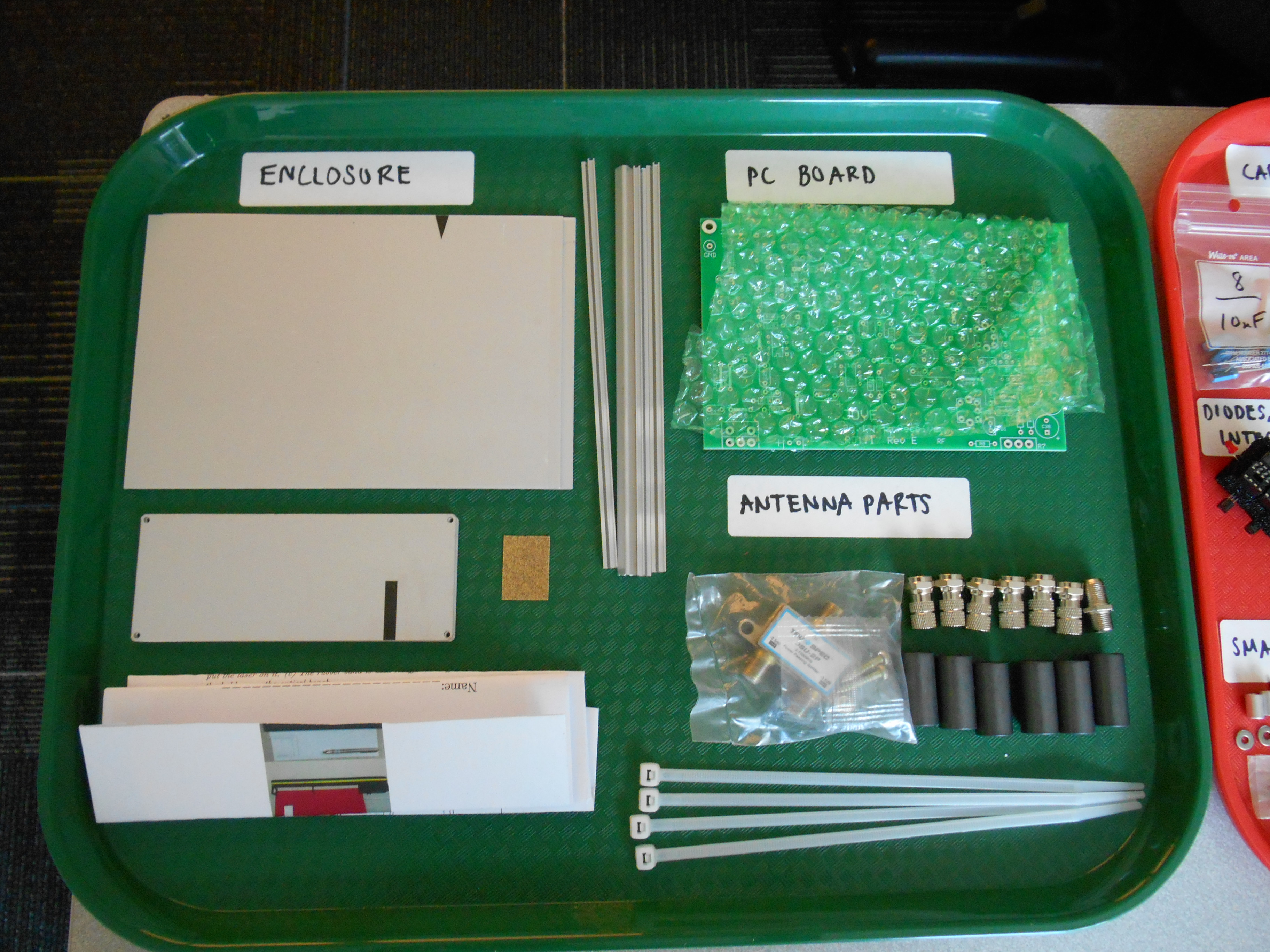
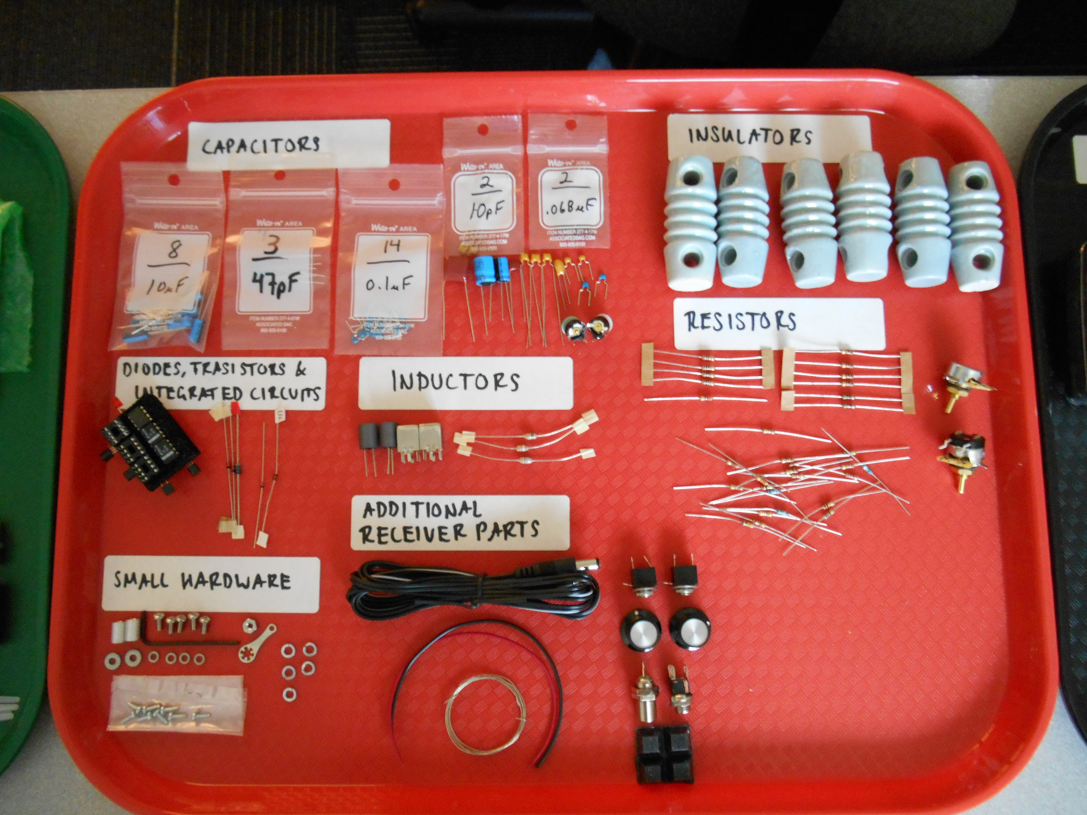
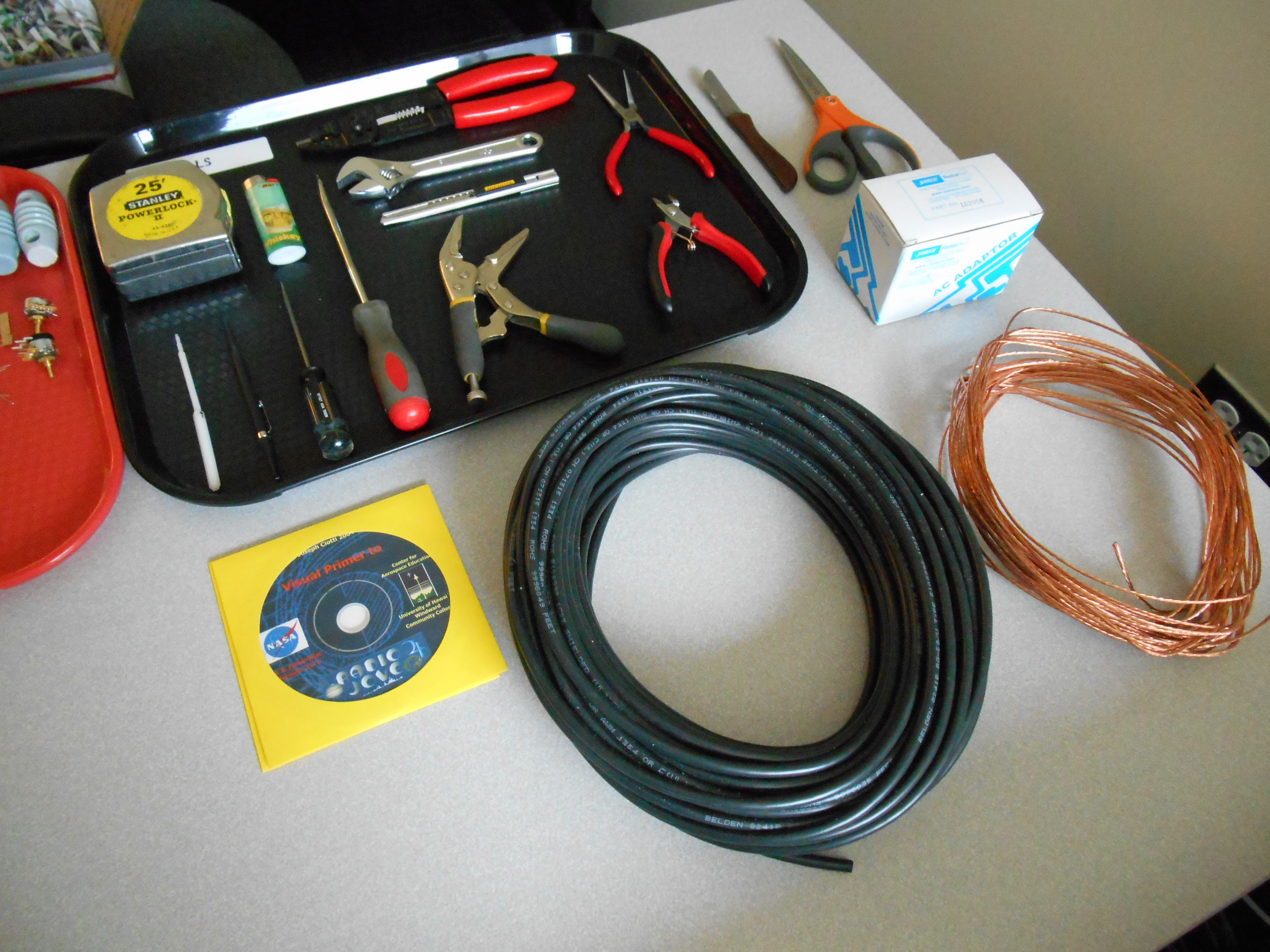
All the provided components and tools were accounted for apart from a 2.1mm plug with a 72 inch cord and lock washer (though these are easy to purchase from various DIY stores).
According to the literature provided, the radio antenna (composed of two dipoles) needs a ground area of approximately 30 feet (9.144m) North to South by 45 feet (13.716m) East to West. It also needs to be situated as far away from buildings and power lines as possible due to the high probability of electrical interference
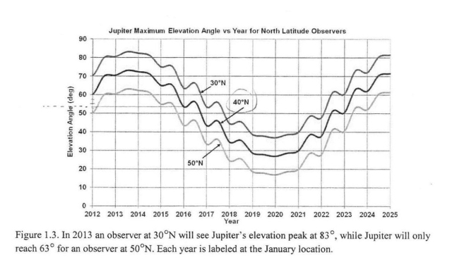
As the latitude that we will be observing from here in Boulder, Colorado is 40°N, using figure 1.3 provided by the manual (see below) the elevation of Jupiter during the planned observation period (July 2016) can be seen to be between 53° and 56°, thus giving an average of 54.5°.
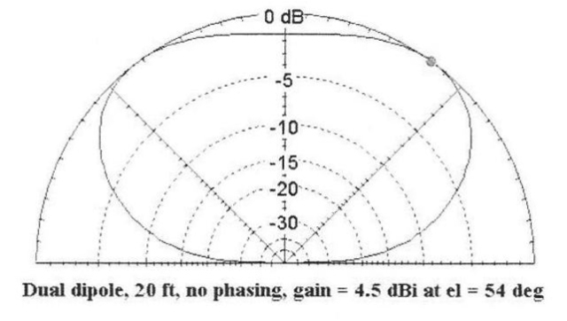
From figure 1.4 in the manual therefore (see above) the antenna pattern should be like the pattern above and the appropriate antenna size to use should be 20ft.
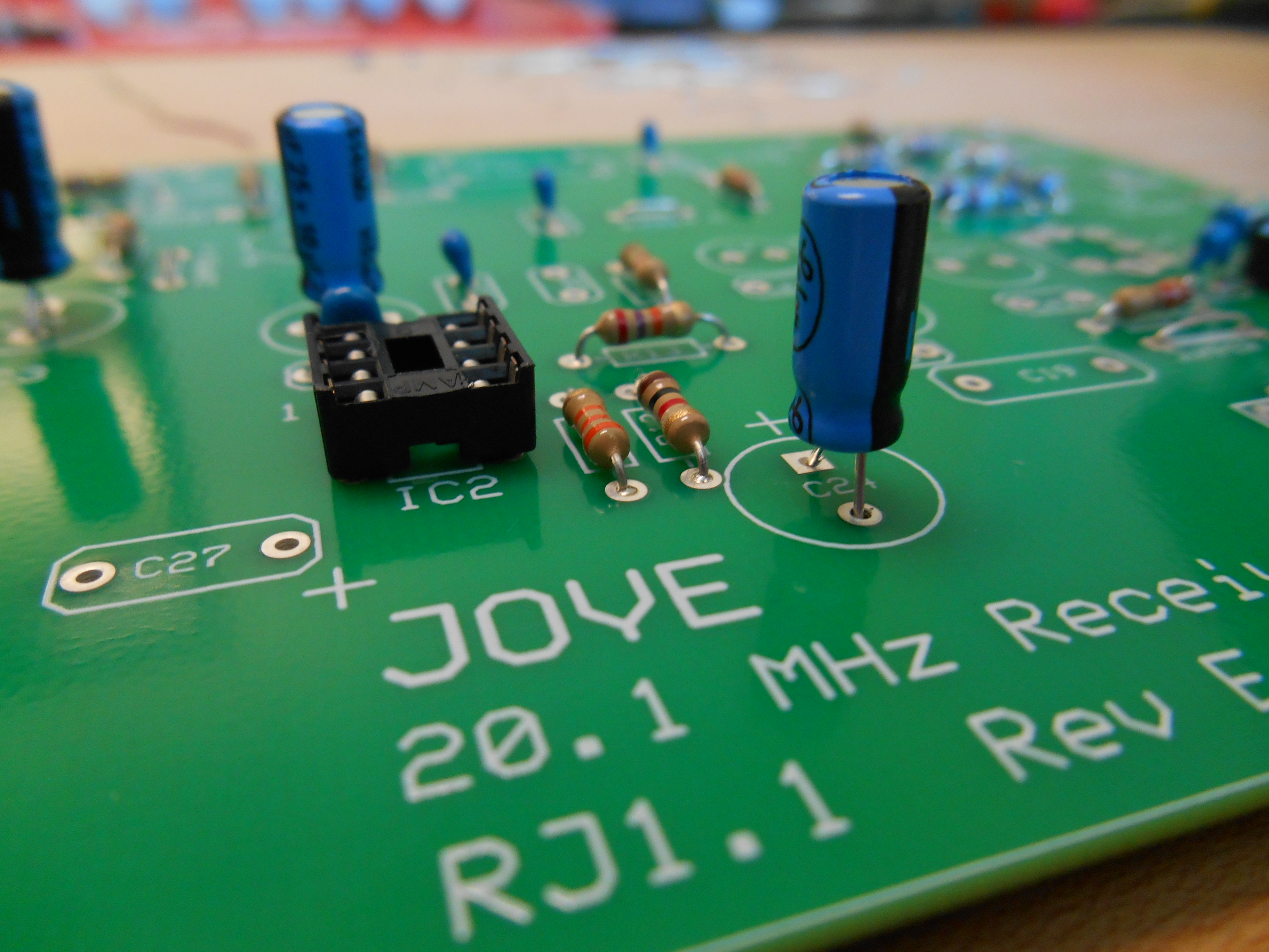
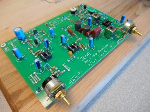
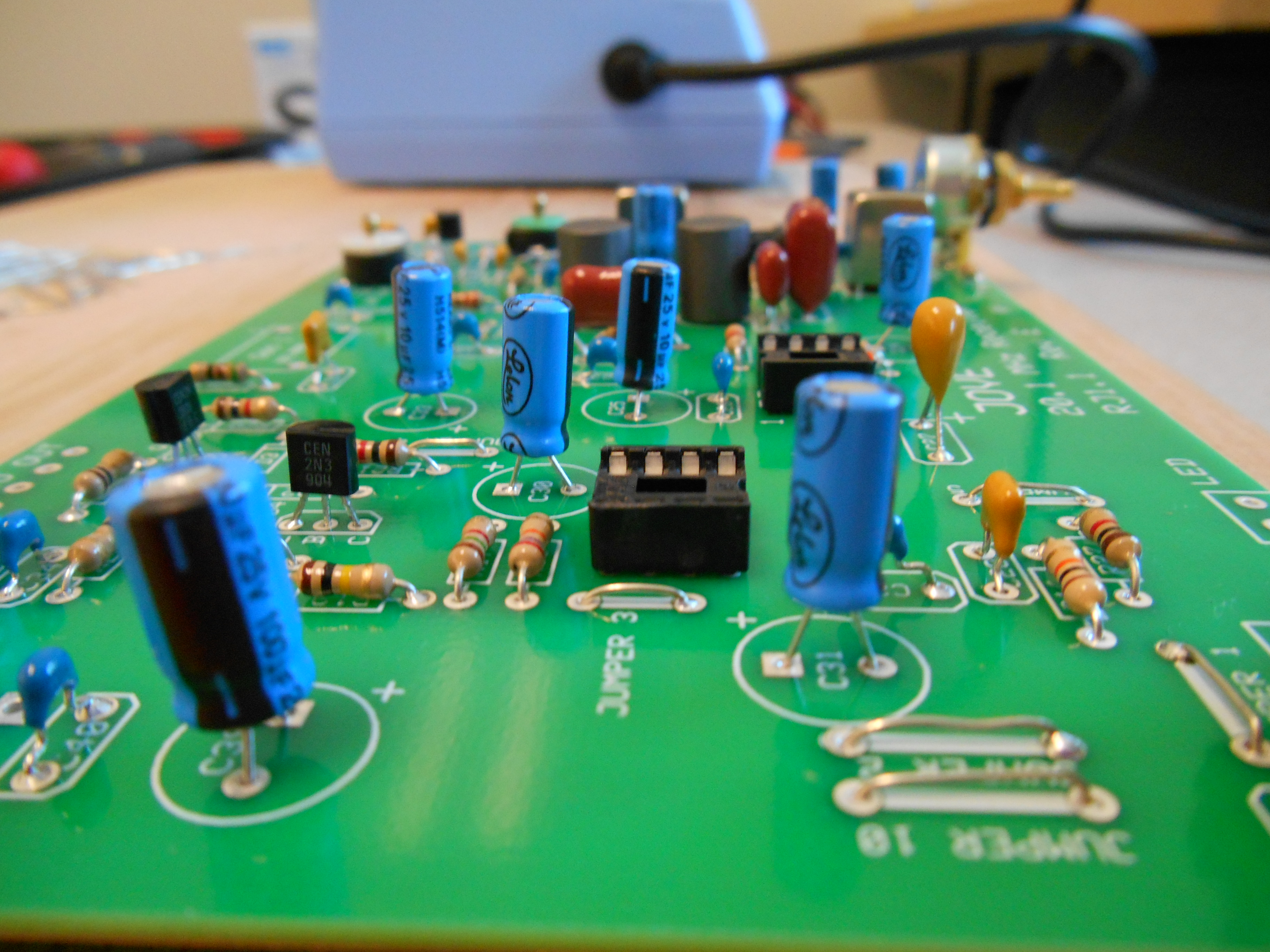
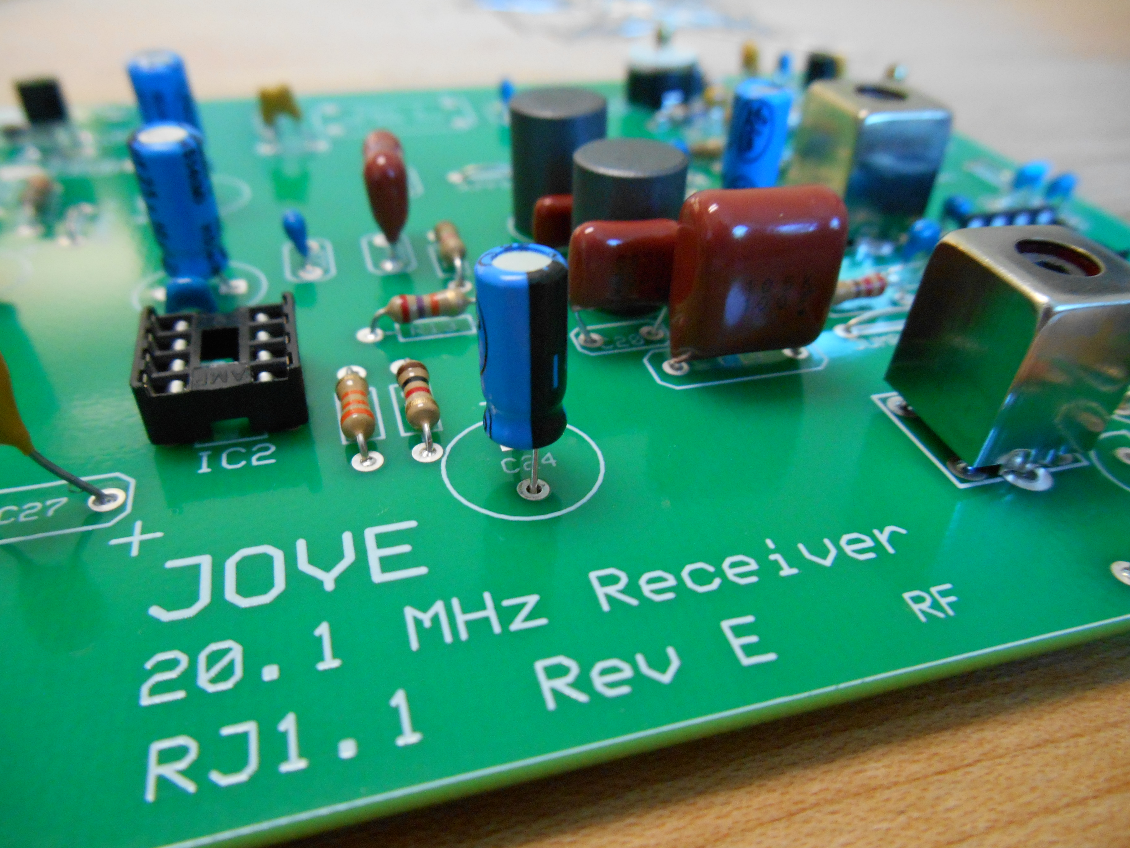
Once the antenna field dimensions had been determined, I began to work on the soldering of the circuit. When following the instructions and provided circuit schematic with care, the process was fairly straight forward (with only one minor mishap resulting in the demise of a 0.1uF ceramic capacitor) and took roughly 9.5 hours to complete overall not taking into account the delay in acquiring a replacement capacitor.
-
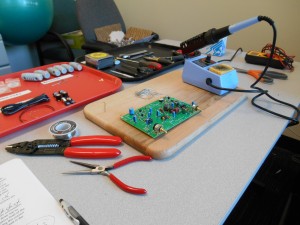
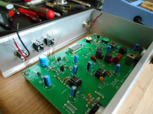
- The work area
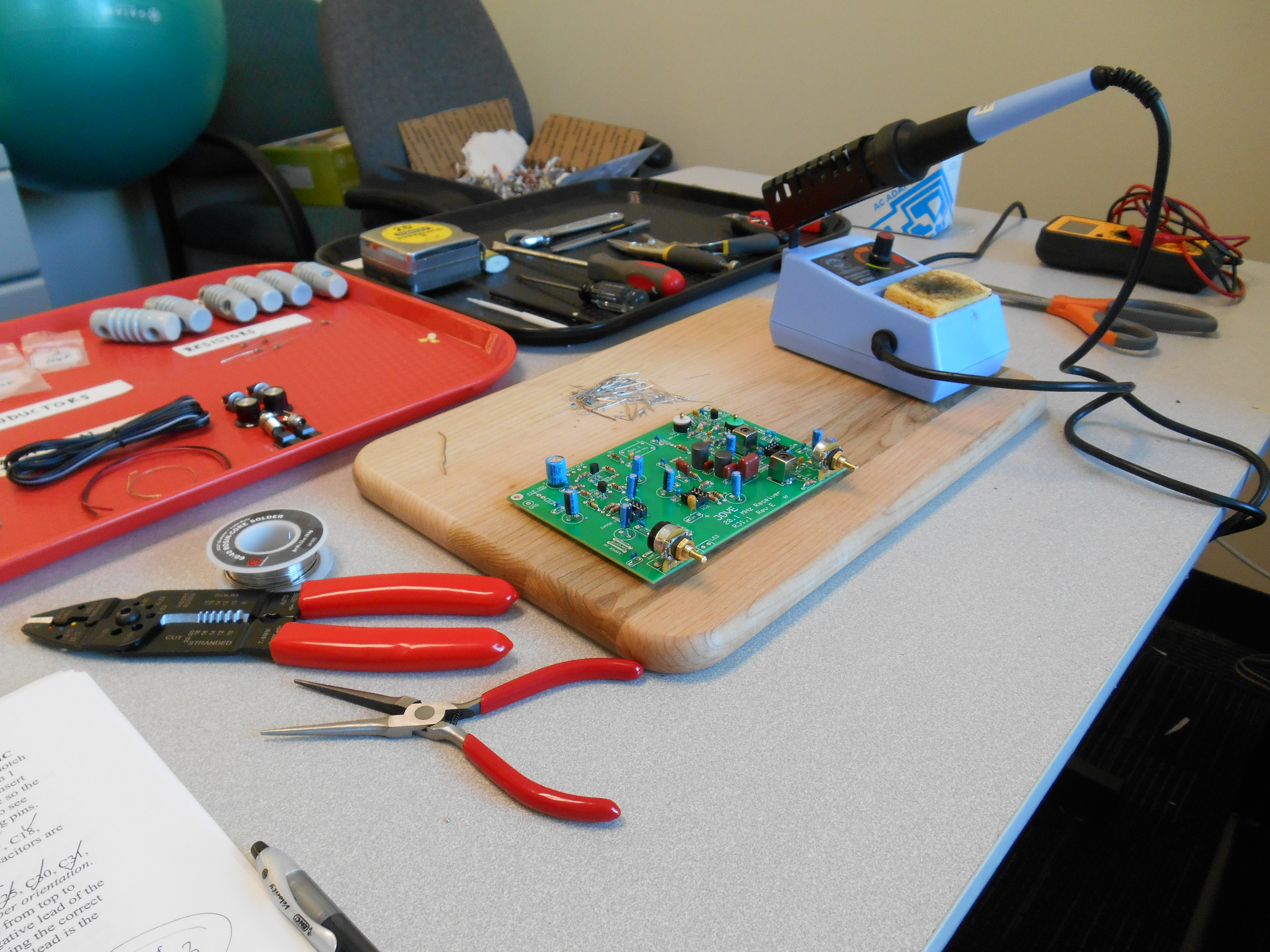
-
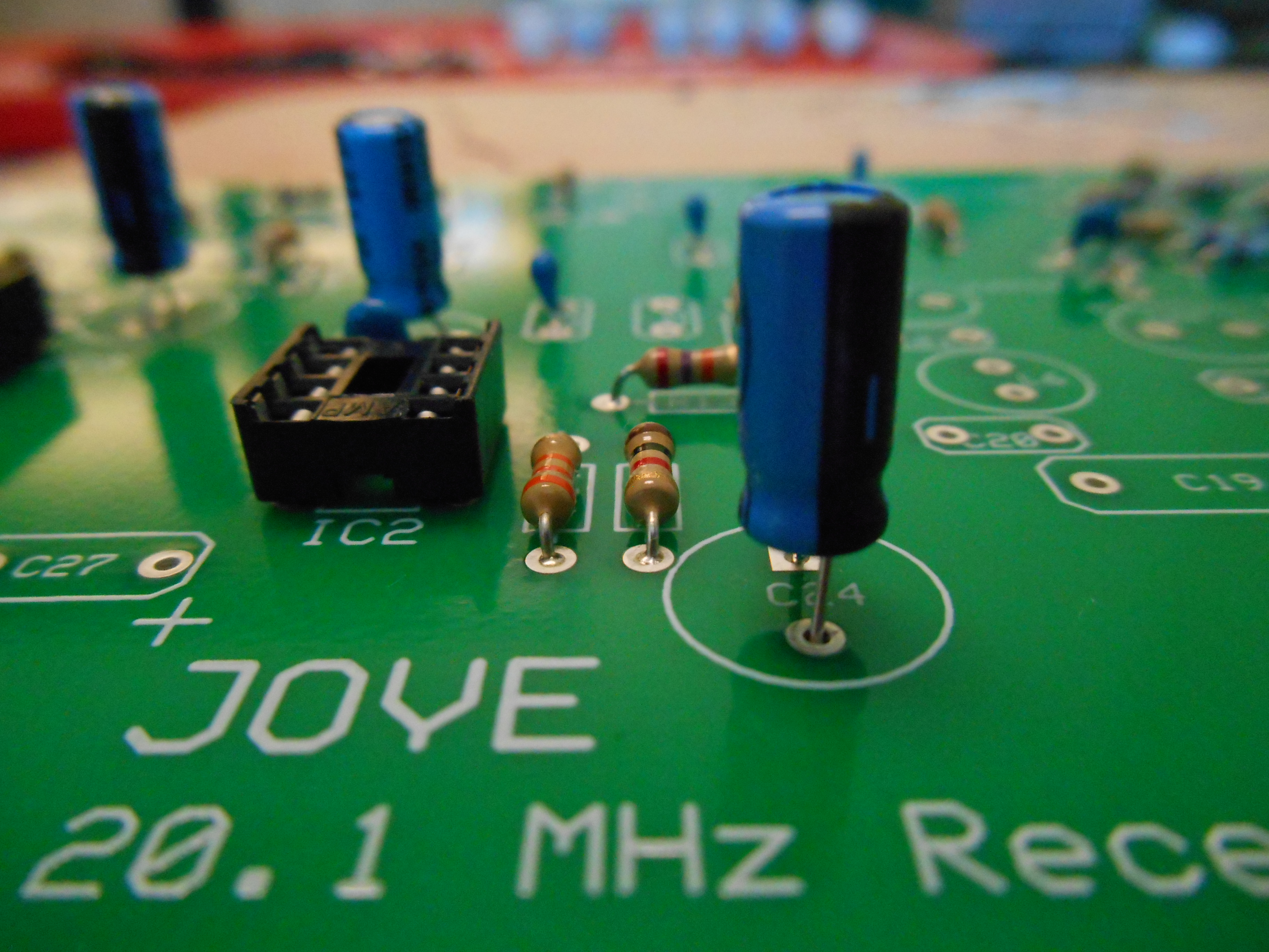
- Soldering in progress

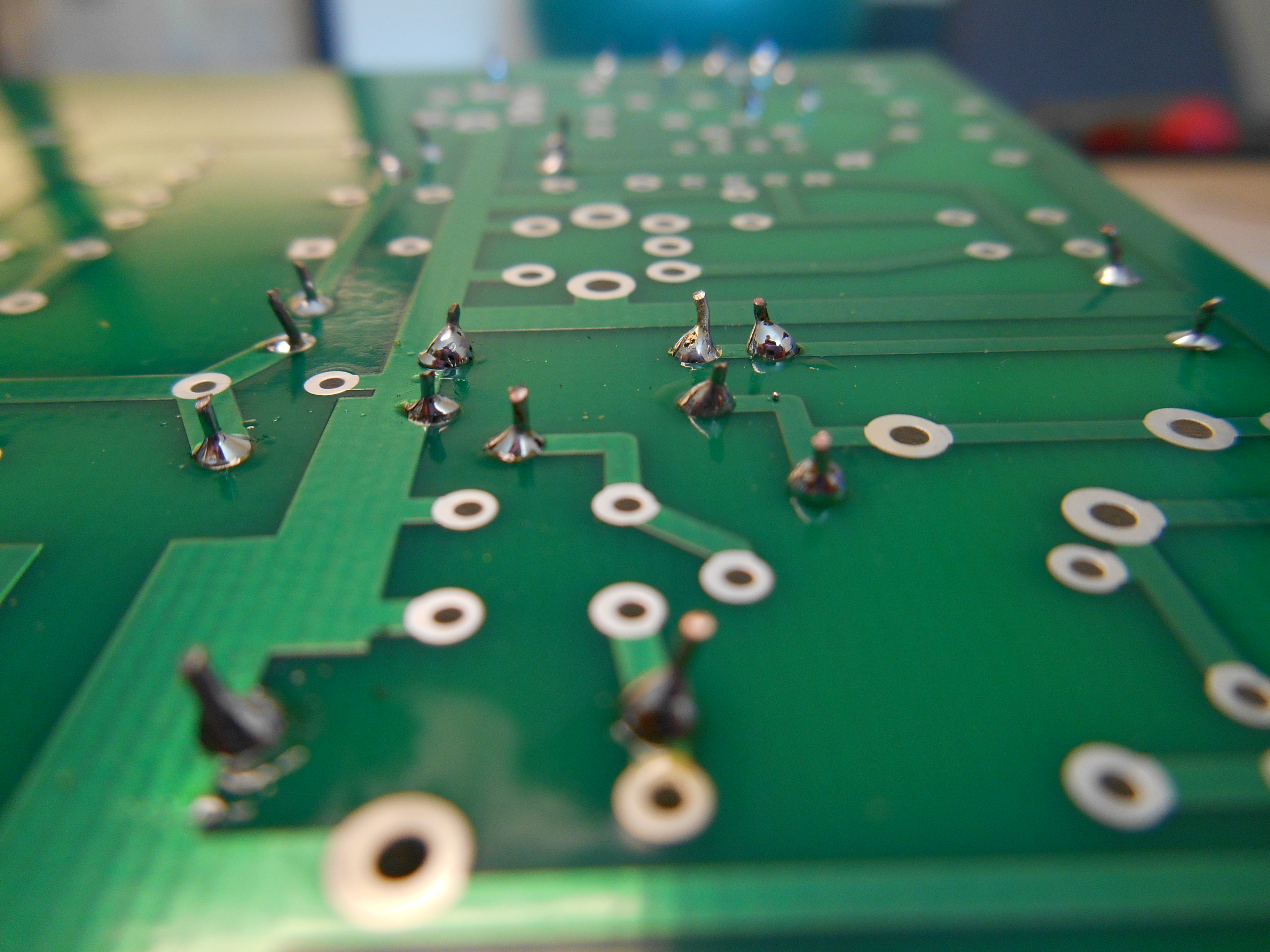
-

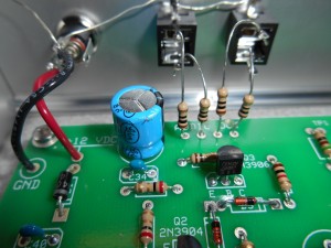
- Close up of solder joints
By Friday the 17th, the majority of the soldering was done and the next step was to begin construction of the receiver enclosure.
Constructing the enclosure
![DSCN0135[1]](https://lasp.colorado.edu/mop/files/2016/06/DSCN01351.jpg)
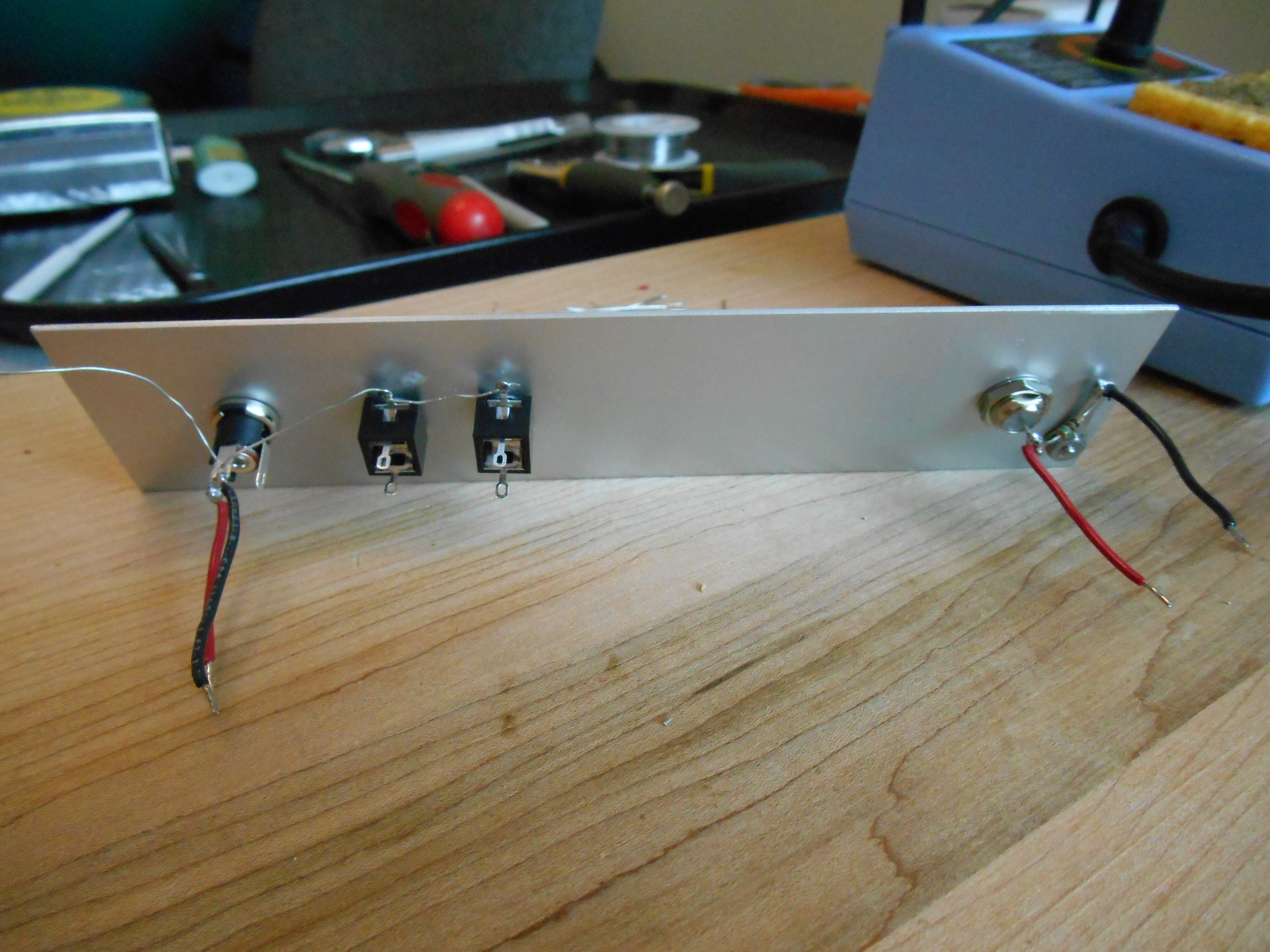
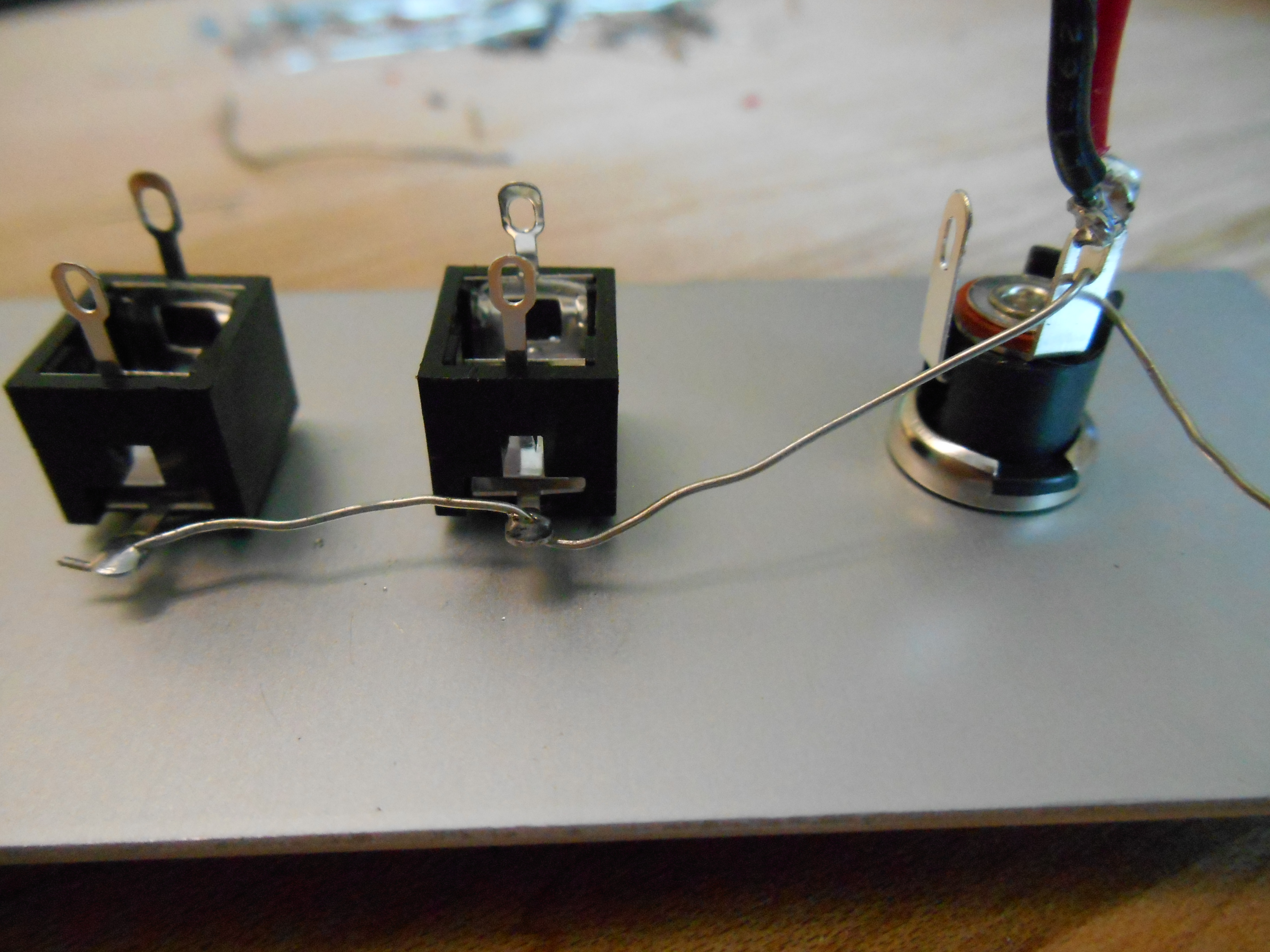
First the rear panel had to be wired with the audio, power and antenna inputs installed (see images below). Once this was done, the rest of the enclosure could be assembled and built around the PC board, with the bottom panel installed last. The top panel will not be installed until the receiver has been fully tested and tuned, as easy access to the circuit will be needed if any problems with the circuit need to be fixed.
-

- Rear panel
-

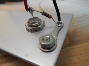
- Wiring of audio and power connectors
-
- Wiring of antenna connector

-
- Building enclosure around PC board

-
- Soldering audio and power connectors

-
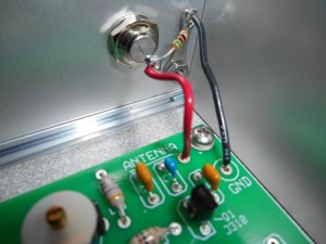
- Soldering antenna connector

By the 24th, the receiver was ready to be tested and the antenna constructed!
«Return to the Radio Jove Blog page