
Spacecraft Specs
Spacecraft Structure

CAD Diagram of the Spacecraft Structure
Structural Diagrams:
- SNOE expanded diagram
- SNOE baseplate diagram
- Spacecraft and launch vehicle diagram
- Launch vehicle dynamic envelope diagram
- Mass properties diagram
Structure-related Photographs:
- Central plate exterior
- Central plate interior
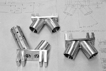
- Launch adapter brackets
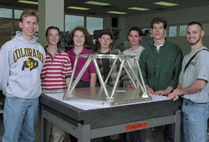
- Student structures team with launch adapter
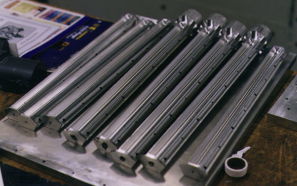
- Solar panel axial support struts
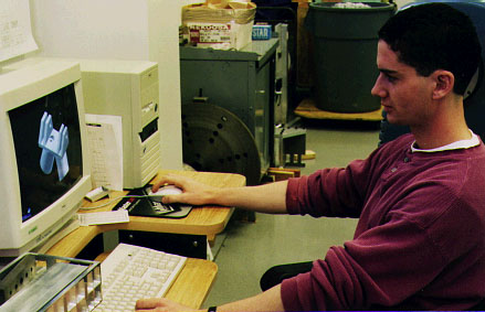
- CAD/CAM machining
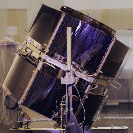
- S/C structure ready for qualification testing
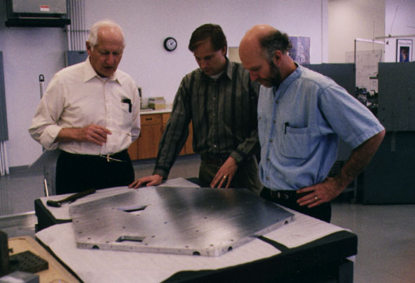
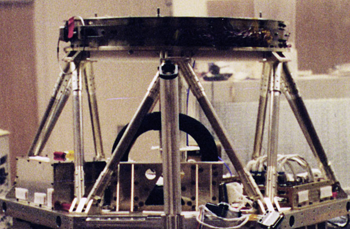
- Launch adapter and central plate
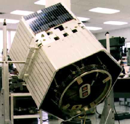
- Completed spacecraft (without radiators and blankets)
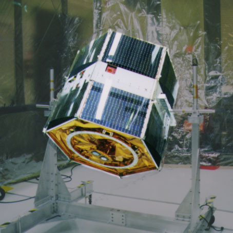
- Completed spacecraft (with radiators and blankets)
This page describes the SNOE spacecraft structural design and component layout. To meet the low cost objective and the science requirements a spin stabilized spacecraft was chosen. The structure consists of two hexagonal solar arrays that attach to a central mounting plate. The mounting plate supports the spacecraft electronics and equipment, as well as the scientific instruments. These units mount to both sides of the mounting plate. Two patch antennas protrude slightly above the ends each solar array. Attached in a band to the periphery of the central support plate, between the solar arrays, are six thermal radiator plates. These plates have apertures, through which the instruments, and two horizon crossing indicators, observe. Thermal blankets cover the open hexagonal ends of the spacecraft.
A key consideration in the construction of the spacecraft is to configure the payload to produce spin stability . Trade studies were performed on the spacecraft design to arrive at the present design. Orientation in orbit was balanced against power requirements (and solar cell collector area) to arrive at this final layout. In each design iteration the payload height was shortened, and the mass was distributed to the outermost locations on the mounting plate. The design shown above is spin stable, with spin to transverse axes ratios of 1.2, significantly larger than the 1.05 necessary for spin stability.
A second consideration is the mass of the spacecraft structure. The tradeoff on this issue balances cost, mass, and ease of fabrication. Metals used in the assembly are principally aluminum, with some aluminum honeycomb (solar panels), and titanium (thermal flexures). The final weight of the fully integrated spacecraft and instruments is 254 pounds.
The structural solution to the spacecraft design involves four primary structural components: 1) the spacecraft equipment and instrument mounting plate; 2) the adapter structure that mates the spacecraft to the launch vehicle. This structure has provision for a separation assembly (marmon clamp and actuator) to release the spacecraft on orbit after positioning and spin-up; 3) two solar array assemblies and their support structure; and 4) two antenna masts.
The central mounting plate provides support for the spacecraft electronics, instruments and cables, and the launch adapter structure. It mounts both of the solar array structures and the antenna mast assemblies. It provides also a thermal path for heat generated in the interior of the spacecraft to reach the thermal radiators. The central mounting plate is fabricated from two weight-relieved alumnium plates bolted together in a clamshell arrangement.
The launch vehicle adapter structure mates the spacecraft to the launch vehicle. The assembly consists of twelve struts (1 inch diameter and .083 inch wall thickness) which connect the central plate to a 23.25 inch diameter marmon clamp on the launch vehicle end. The struts are attached to the marmon clamp and central plate in pairs through connection blocks machined out of aluminum. The separation fixture details have been developed in accordance to the details outlined in the Payload Users Interface Control Document (ICD). During integration the adapter structure will be attached to the launch vehicle’s marmon clamp using a clamp band.
The two hexagonal solar array assemblies consist of 6, 0.5″ thick honeycomb panels that are approximately 18.75″ wide by 13.5″ tall. Mounted to each panel are two strings of solar cells; the cells are bonded to the surface of the honeycomb material using traditional mounting techniques. Two edges of each honeycomb panel attach to axial supports which serve as columns providing axial (spin axis) rigidity. Each set of six assembled solar arrays is a monocoque, using the panels as shear ties. The assembled structure joins to the spacecraft by bolting the axial supports to thermal flexures which in turn are bolted to the central mounting plate. The thermal flexures consist of a thin (0.1 inch) “blade” of titanium 0.5in in length. This approach allows the spacecraft equipment to be managed thermally without concern for the varying solar panel temperatures. The construction of the top and bottom solar array structures is essentially identical. Each end of the spacecraft requires a closeout of MLI blanket and Beta cloth for thermal reasons. On the bottom end the spacecraft adapter structure will provide the necessary support for this material; on the top end of the structure a “spider” is shown to provide the necessary tie downs and fastening locations.
There are two patch antennas located on the spin axis at each end of the spacecraft. The antennas consist of a support tube and a thin plate. This assembly mounts to each side of the central mounting plate. The column provides structural support for the antenna, and precisely positions it so that the ground plane of the antenna sits above the solar panel.
Attached to the central mounting plate, around the periphery of the hex, are six 0.1″ aluminum radiator panels. Three of these panels have apertures for the science instruments and sensors located on the spacecraft. The radiators are coated with a durable ceramic surface to maintain radiative properties so that operating temperatures are controlled.
A finite element model of the spacecraft structure was constructed using Cosmos/M. The model consists of 125 tri-shell, quad-shell and 3 layer composite elements. Modal analysis for the first ten modes were analyzed, and simulations were run to determine mode response and displacements. The structural model includes the adapter structure, the mounting plate and solar arrays. Masses representing most of the spacecraft electrical and sensor components, as well as the spacecraft instruments, were also included. The first mode frequency is 40 Hz, and corresponds to a cantilever mode shape off the launch adapter marmon clamp assembly.