
C & DH
Diagram
 Hardware Overview
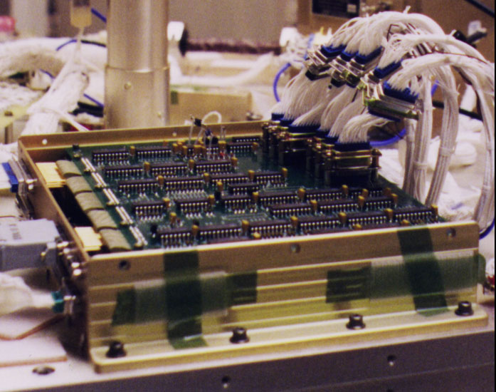
The Command and Data Handling (C&DH) system consists of a flight computer and five I/O blocks on two daughter boards. These I/O blocks handle interfacing the computer to all S/C sub-systems. This hardware primarily consists of digital logic circuitry instantiated using ACTEL ACT1 FPGA\325s. In cases where large telemetry volumes exist, FIFO\325s are used for data buffering, thus lowering S/C computer/telemetry interaction times. Lowering these times is a self-imposed requirement for the C&DH hardware system that yields lower computer throughput requirements. All of the unique C&DH circuitry resides on two PC boards that attach directly to a dedicated port on the S/C computer.
The flight computer used is an SC4A Single Board Spaceflight Computer developed by Southwest Research Institute (SwRI). Instrumentation and Space Research Division. It includes a 16-bit 80C186 central processor with a clock frequency of 10 MHz. It is MS-DOS and VRTX compatible. The throughput capacity is estimated at 0.77 MIPS. On-board memory includes 512K Bytes RAM, 256K Bytes EEPROM, and 64K Bytes UVPROM all with error detection and correction. Up to 24M Bytes of mass memory is also provided. Communication capability includes 32 12-bit analog input channels, 4 12-bit analog output channels, a two channel RS-422 Serial I/O port, and 16 input/output Parallel I/O (total 32). The computer uses memory mapped I/O, providing 16 bit word reads or writes per instruction cycle. Along with interrupts, this will be the main method of interface to the computer.
Software Overview
The software development language is ANSI C. Development of the software is on a MS-DOS Intel 80486 personal computer. The development computer uses the RS-422 port on the SC-4A for loading software and performing operation simulations. The processor software consists of high-level and low-level functions that handle all hardware interrupts and timed events. Command storage and management, data-gathering and housekeeping are all performed by the software. A modular design constraint is employed to simplify the software and ease implementation.
SNOE uses a packetized telemetry data scheme based upon the recommendations by the Consultative Committee for Space Data Systems (CCSDS). The CCSDS is an international organization composed of representatives from the world’s space agencies. Compared to a traditional time-division multiplexed telemetry system, packetized telemetry systems provide substantial design freedom: any number of different packets can be developed to hold the spacecraft’s science, engineering and ancillary data. Generating packets sometimes involves complex sets of functions that are, just as all functions performed by the SNOE software, grouped into software modules. Since the SNOE software handles functions traditionally implemented in hardware, the software modules are called from a main loop that is rigorously deterministic in its timing.
SNOE Telemetry
There are two telemetry channels from the SNOE satellite. The first is a low-rate (512 bits per second) channel that will be used in case of emergency. The channel has a safety factor of over 9 dB, providing a communication link in even the most extreme conditions. The 512 bps bandwidth channel has room for only real-time data, primarily engineering telemetry, leaving science data and playback data for the high-rate channel. Even with the limited bandwidth, it is still possible to transmit both engineering and science data in real-time on the low-rate channel. The second telemetry channel is a high-rate communication channel that transmits at 128 kbps. This channel has the bandwidth capacity to transmit engineering, science and playback data. Both channels are NASA compatible PCM/PSK/PM.
Both telemetry channels utilize fixed-length transfer frames with variable-length source packets inside the frames. The transfer frame lengths on each channel are not equal, since each is derived from transmission rate and desired frame update rate. The desired real-time frame update rate is nominally 2 seconds, a value based solely on the desires of mission operators. This equates to a frame length of 1024 bits on the low-rate channel. Frame length selection on the high-rate channel, discussed below, is more involved. Simple CRC error checking is performed on a frame-by-frame basis, as neither telemetry stream is Reed-Solomon encoded. Additionally, SNOE will not utilize the optional transfer frame secondary header. The transfer frame overhead then equates to a header of 48 bits, a 32-bit trailer for a Frame Acceptance and Reporting Mechanism (FARM)2, and a 16-bit CRC code, for a total of 96 bits. This leaves a 464 bps real-time bandwidth for data on the low-rate channel.
Originally, SNOE designers intended to utilize the high-rate channel solely for playback data. The bandwidth analysis for the high-rate channel would then be identical to the low-rate. However, if the SNOE team used the low-rate channel as the only means to a real-time communication link, telemetering anything but engineering data on the low-rate channel would effectively choke the bandwidth and cause severely increased engineering data update delays for the ground crew. In other words, the operations team would have to settle for either engineering data only, science data with limited engineering data, or neither during a memory dump. Clearly, the limited bandwidth on the low-rate channel complicates the downlink. Therefore, SNOE uses part of the high-rate channel as a “virtual” low-rate channel for real-time communications.
Source Packets
The available bandwidth for each channel is used to hold flexible data structures called “Source Packets.” The SNOE telemetry system allows for packets to overlap frame boundaries in both the low-rate and high-rate channels. This unconventional design decision maximizes the bandwidth use, eliminating the so-called “slop”, or unused portion of a transfer frame. Most telemetry systems steer clear of this technique due to the fact that a loss of a single frame may affect data in adjacent frames. The SNOE team can afford this risk since loss of an occasional piece of data does not cripple the SNOE science objectives. This is a classic example of a small satellite trade-off that the SNOE engineering team has used to its advantage.
Pre-defined packet descriptions:
- Communication Status
use: command verification and comm. link status
update rate: 2 seconds - Subsystem Status
use: ADCS, instrument status, C&DH parameters
update rate: Spin Period - General Engineering
use: Temperatures, Power, C&DH Parameters
update: 60 seconds - Critical Engineering (Contains duplicate items from main three engineering packets for low-rate channel science telemetry mode)
use: Minimal command verification, comm. link status, power, ADCS, and C&DH parameters.
update rate: 6 seconds
Programmable Telemetry Packets
Although it is a term typically viewed with trepidation, SNOE uses ‘programmable’ telemetry: items in some packets can be selected in a custom manner during flight. There are two such packets on-board the spacecraft: the Programmable Rapid Sample Packet and the Programmable Engineering Packet. Each telemetry item on-board is associated with an ID. These ID’s are then used to populate the programmable packets through ground commands. Both packets limit the total number of items in each, but neither pre-define the contents of any ‘slot’ within a packet. The Rapid Sample Packet allows operations personnel to specify which telemetry ID’s, and hence which telemetry items, to sample as fast as 10 Hz. Due to the high frequency capability, only four items are allowed at a time. When commanded, the flight software will then sample the four telemetry items and plac ten consecutive samples of each in the packet for transmission. The Programmable Engineering Packet allows for a larger set of items (up to 28) at frequency ranges much lower than the Rapid Sample Packet. These packets provide a flexible means of de-bugging problems on the spacecraft, as well as allowing for telemetry arrangements not anticipated by the pre-defined packets.