Instruments
Ultraviolet Spectrometer
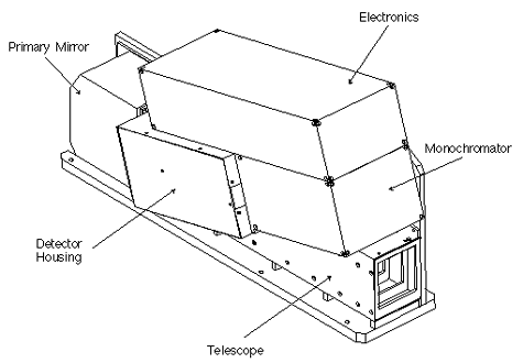
The primary function of the ultraviolet spectrometer (UVS) is to measure the density of nitric oxide between the altitudes of 100 and 200 km in the terrestrial upper atmosphere by observing the (1,0) and (0,1) gamma bands. The UVS design is similar to instruments flown on the Solar Mesospheric Explorer (SME), Pioneer Venus, and several rocket flights. It consists of an Ebert-Fastie spectrometer, an off-axis telescope, and two Hamamatsu phototube detectors. The spectrometer has a focal length of 125 mm and uses a 3600 l/mm mechanically ruled plane grating which produces a dispersion of 1.8 nm/mm at the detectors. The phototubes each have fused silica windows and a cesium telluride photocathode. The telescope is an off-axis parabola with a 250 mm focal length and is used to image the spectrometer slit on the limb. The combination of the spectrometer and the detectors produces a spacing of 22 nm between the two channels and the exit slits are sized to give each detector a 3.7 nm bandpass. The grating in the spectrometer will be set to place the (1,0) gamma band ( 215 nm) on one detector and the (0,1) gamma band (237 nm) on the other detector. Both channels have a sensitivity of 450 counts/second/kiloRayleigh.
The UVS is mounted with its optical axis perpendicular to the spin axis of the S/C. Its telescope images the entrance slit of the spectrometer on the limb with the long axis of the slit parallel to the horizon. The image of the slit on the limb is 3.5 km high, which determines the fundamental altitude resolution of the instrument. The integration time of the is set to 27 milliseconds. To minimize requirements on the S/C, data are stored for the downward limb scan only. Allowing for some overscan, this produces 65 samples per spin from each channel. The storage operation is initiated by a signal derived from the horizon crossing indicator in the ADCS. The data are stored in a buffer which is emptied, time-tagged, and stored once per spin by the S/C microprocessor.
Auroral Photometer
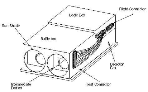
The auroral photometer (AP) is a two-channel broad-band instrument that is used to determine the energy deposited in the upper atmosphere by energetic auroral electrons. It is similar to airglow photometers developed by LASP and flown on OGO-5 and -6 in the late 1960’s. The channels consist of two Hamamatsu phototube detectors, a UV filter for each channel, and a field of view limiter for each channel. Both channels have circular fields of view, 11 degree full-cone. The detectors are identical phototubes with magnesium fluoride (MgF2) windows and cesium iodide (CsI) photocathodes. Channel A has a calcium fluoride (CaF2) filter placed in front of the detector and channel B has a barium fluoride (BaF2) filter. The combination of the CsI photocathode and the CaF2 filter produces a bandpass from 125 to 180 nm for channel A, allowing a combined measurement of the LBH bands, the OI doublet at 135.6 nm, and the OI triplet at 130.4 nm. Channel B has a 135 to 180 nm bandpass, providing a measurement of the LBH bands and the OI doublet at 135.6 nm with the exclusion of the OI triplet at 130.4 nm. The sensitivity of channel A at 130.4 nm is 23 counts/second/Rayleigh and the sensitivity of channel B at 135.6 nm is 26 counts/second/Rayleigh. The AP and UVS photomultiplier electronics are identical, resulting in significant economies in fabrication and operation.
As with the UVS, the AP is mounted with its optical axis perpendicular to the S/C spin axis. The AP produces continuous data but at a much lower rate than the UVS. Only the downward- looking 60° of each spin will be stored. The integration time for each channel is set to 63 milliseconds which provides 32 samples per channel per spin. Data from the AP are stored in its buffer, which is emptied once per spin by the S/C microprocessor.
Solar X-Ray Photometer
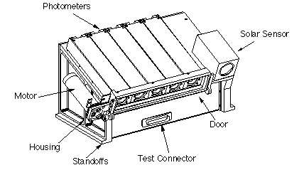
The solar X-ray photometer (SXP) measures the solar irradiance at wavelengths from 2 to 35 nm in the soft X-ray to hard EUV (or “XUV”) portion of the solar spectrum. Each photometer channel consists of a silicon photodiode; wavelength selection is accomplished by thin metallic films deposited directly onto the diode surface. A door with a fused silica window covers the diodes. When it is open, the diodes measure solar X-rays plus some visible light contamination. When it is closed, the X-rays are blocked and only the visible light is measured. By subtracting the door-closed measurment from the door-open measurement, the X-ray fluxes are obtained.
Five photodiodes are flown. Coatings are selected so that overlapping bandpasses can be used to isolate key parts of the solar spectrum at low resolution. The coatings are: Tin, Titanium, Zirconium/Titanium, and Alumninum/Carbon. The fifth diode has no coating – it is used to measure the visible light transmission of the fused silica window. The approximate bandpasses of the diodes are:
- Sn: 2-8 nm
- Ti: 2-16 nm
- Zr/Ti: 5-20 nm
- Al/C: 15-35 nm
The sensitivity of each channel is approximately 10 electrons per photon. The diode current is converted to a freqeuncy at 50 kHz/nA and counted by the same type of electronics used in the UVS and AP. The field of view is 70 degrees full cone. The SXP takes 12 measurements per spin, centered on the zenith, with a 63 second integration time. Thus, it obtains an integrated solar measurement once per orbit, when the sun is near the zenith. The nominal operations plan calls for a door-open measurement on every other orbit. Data is stored in a buffer that is emptied once per spin by the S/C microprocessor, in the same manner as the UVS and AP.
Global Positioning System
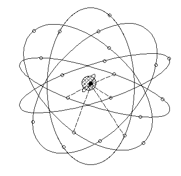
The Global Positioning System (GPS) consists of a constellation of 24 Earth- orbiting satellites split between six orbital planes. The satellites constantly broadcast their positions down to Earth. The retrieval and decoding of these signals using an antenna and GPS receiver allow anyone to locate their position with a guaranteed 100 meter accuracy. GPS receivers on spacecraft allow for orbit and attitude determination. The SNOE spacecraft will fly a microGPS Bit-Grabber Space Receiver (BGSR) which will record data and send it to the ground in the satellite playback data. No on-board processing will be done. The GPS instrument was provided by JPL and the data will be analyzed by both JPL and the University of Colorado. The entire instrument is quite small and very low power. The antenna is a 7.3 cm square ceramic patch antenna.The receiver is approximately 200 cubic centimeters weighing less than .5 kg. The GPS instrument will sample GPS signals. It will take and store short duration (several milliseconds) samples of the composite GPS signal at the CA bandwidth. The samples will be programmable in duration and frequency and will be post-processed to recover the GPS observables. Nominally, the BGSR will sample several milliseconds of data on three selected spins of every orbit. The data received from the BGSR will be processed using ground-based software that can be run on a desktop computer. The software will be able to produce spacecraft orbits, attitude measurements, and clock fixes based on the telemetered GPS signal samples. As the mission progresses, these data may be provided for uplink to the spacecraft computer.


