Instrument Design
SIM Block Diagram
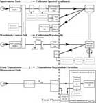
The figure on the right shows a block diagram for the SIM instrument. The operation of the instrument requires 3 independent optical paths. The measurement light path (shown in red) is the path that light follows when going from the Sun through a precisely measured entrance slit to the prism where it is dispersed to give the spectrum on each of the focal plane detectors. Shown in blue is the light path that illuminates the CCD located in the focal plane that acts as an encoder of prism rotation angle. Shown in green is the light path that couples the two instruments for direct prism transmission calibration. All of these light paths and the associated mechanisms will be described below.
Optical Design
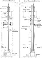
The prism design is based, in part, on the 1910 design of Fèry. The prism has a concave front surface and a convex, aluminized back surface that focuses and disperses the light beam on to the instrument focal plane. Thus only one optical element is used in the measurement of solar radiation. The focal plane contains the electrical substitution radiometer (ESR) and four additional photodiode detectors that concurrently detect solar radiation as the prism drive is rotated. The resolution of the spectrometer is dependent on the spectrometers geometry and the index of refraction of the prism glass. The prism spectrometer has a resolution varying from 0.25 nm in the ultraviolet to 33 nm in the infrared. The prism is made of Suprasil 300 (Hereaus Amersil, Inc.), a high purity and low OH content fused silica product that has very good radiation hardness properties. The low OH content of the glass ensures good optical transmission throughout the infrared part of the spectrum.
SIM contains two completely independent and identical (mirror-image) spectrometers. These two spectrometers provide in-flight redundancy and self-calibration. Each SIM spectrometer is also equipped with a hard radiation trap (HRT) to prevent excessive exposure to energetic radiation that will degrade the transmission of the prism over time. The HRT is a retractable filter that will be moved out of the optical path when absolute solar irradiance measurements are performed, but placed in the beam at other times so the acquisition of spectra can continue in a protected mode. The filter is also made of Suprasil 300. The filter is wedged and tilted with respect to the dispersion axis of the instrument to prevent the appearance of etalon effects in the solar spectrum when the filter is in the incoming light beam.
The detectors and optical elements in SIM are protected from exposure to aerosol particulates and volatile organic vapors by building the instrument case as a vacuum/pressure enclosed vessel. This is to prevent environmental contamination from changing the pre-flight calibration, and to inhibit organic materials from depositing on the optical elements where in-flight UV exposure will cause these hydrocarbons to irreversibly change the transmission of the optical components. SIM will be evacuated and backfilled with 1.2 atmospheres of argon prior to launch; and after on-orbit outgassing, the instrument vent valve will be opened to evacuate the instrument. Then the vacuum door will be opened to allow normal instrument operation. The vacuum door is equipped with fused silica windows, so instrument checkout and early orbit operations can begin without opening the door.
ESR and Focal Plane Photodiodes
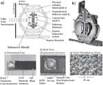
The SIM ESR operates on the same principal and uses the same detector methodology as the active cavity radiometer for TIM. However, the light signals emerging from the spectrometer are ~1000 times smaller; so, a different thermal/mechanical design is needed for this detector. Instead of using a cone to absorb radiation, a bolometer made of diamond is blackened with nickel phosphorous black (NiP) to absorb the incoming radiation from the spectrometer, and the change in temperature induced by this radiation is detected by thermistors located at each end of the diamond strip. This bolometer is then centered in an optical quality sphere to increase the blackness of the bolometer by allowing the small fraction of light reflected off the black surface to be re-imaged onto the bolometer. Bonded onto the back face of the bolometer is a thin film electrical power replacement resistor. There are two bolometers located inside the spherical cavity; the active bolometer sees light from the spectrometer while the reference does not. The thermistors on the two bolometers are part of a precision AC bridge circuit that maintains an equal temperature on the two bolometers, and bridge balance is achieved by varying the duty cycle of the power applied to the active bolometer. As in the TIM instrument, a shutter modulates the input light beam and the ESR time series data is analyzed in the frequency domain at the shutter fundamental frequency. Typically, two shutter cycles are acquired and the shutter is operated at 0.01 Hz, thus giving a minimum detection of 2.5 nW in a 200 second integration period.
The focal plane photodiodes for SIM are used to acquire the solar spectrum in a “fast-scan” mode in which the prism drive is stepped 1/3 of a slit width per step. This way, the resolution of the spectrometer meets the minimum sampling requirement. To measure the UV and the blue part of the visible spectrum, n-on-p type silicon photodiodes are used; for the red part of the visible spectrum, p-on-n type silicon is used; and InGaAs is used to measure infrared spectrum out to 1.7 µm. Beyond this wavelength, the ESR is used to measure out to 2.4 µm in a special instrument operation mode.
Prism Drive
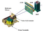
To meet the high accuracy needed for the irradiance measurements, the spectrometer also needs a precision prism drive that has a wavelength error < 150 ppm. This requirement is met by a closed loop wavelength drive system that employs a voice coil actuated turntable to rotate the prism and a charged coupled device (CCD) linear array in the spectrometer’s focal plane to detect the prism rotation angle. This is accomplished by setting up a separate optical path through the spectrometer. Sunlight enters the spectrometer through an entrance slit and impinges on a concave mirror located on the prism’s axis of rotation, and the light is then focused onto the CCD in the focal plane. As the prism rotates the image spot moves along the length of the CCD giving the angle of rotation and therefore the wavelength of light going through each of the detector’s exit slits.


